by Steve Cunningham
In the beginning there was the compact disc. This technology brought forth the digital revolution and, combined with advances in modern computers, allows us today to pack an entire production room worth of equipment into a small laptop bag. Along the way there have been further advances, higher sample rates, and larger bit depths. Digital recording today approaches and in many cases exceeds the finest quality that analog could ever offer.
We can now choose sample rates from the CD’s 44.1 kHz up to 192 kHz, and bit depths from 16 to 24 and even 32 bits. But as these new choices have emerged, various myths about them have tagged along. This month will take a look at these choices, and some of the myths, regarding digital recording. But first, allow me to go into teacher mode and present a brief review.
BRUSHING UP ON THE BASICS
Analog audio can be described in terms of its two main properties: frequency and volume. Frequency represents the time component of analog audio, while volume represents the amplitude or intensity component. Likewise, we can describe digital audio in terms of a time component called sampling, and an amplitude component called quantization.
As most of you know, the first step in the process of digitizing analog audio involves taking snapshots of our analog audio at regular intervals. The number of snapshots (or samples) taken per second is the sampling rate. In general, the higher the sample rate, the more accurately we can reproduce the sound of the original analog audio, particularly with regard to high frequencies. In the next step, the absolute amplitude of each snapshot is measured and converted into a digital number. This measurement and conversion process is called quantization, and the quantity of zeros and ones used to measure the amplitude of a single sample is called the bit depth. In general, a higher bit depth gives us more available dynamic range and a lower noise floor.
DEEPER SAMPLING
When recording analog audio, the “sampling rate” of the recording process is essentially infinite, because analog recording captures virtually all of the amplitude changes that occur over time. In digital recording, the only amplitude changes that are recorded are those that are measured at intervals set by the sampling rate. The Nyquist theorem tells us that the sampling rate must be at least twice the highest frequency we wish to record and reproduce accurately. So to accurately reproduce harmonics that may approach 20 kHz (the upper limit of human hearing), the sampling rate must be at least 40 kHz.
The industry standard for compact discs is 44.1 kHz, giving us a margin of safety as regards Nyquist.
But there’s another issue that must be addressed here. Audio that exceeds the Nyquist limit (in the example above, 20 kHz) must be removed from the input signal using a low-pass, anti-alias filter located before the converter, or aliasing noise will be produced (and it can be quite audible). Here’s why: At its core, sampling represents an amplitude modulation process, much like AM radio. The incoming analog audio modulates the stream of sampling pulses, which are running at the sample rate. This modulation creates sidebands exactly like those created in AM radio. It is the anti-alias low pass filter’s job to block frequencies that could create sidebands in the audible range. In Figure 1, you can see how it does its job.

Note that unlike the sidebands created in AM radio, these digital sidebands are dangerously close in frequency to our audio signal. For example, sampling a 20 kHz signal at 44.1 kHz yields a lower sideband at 24.1 kHz, which is just a handful of semitones away from our sampled signal. This explains the need for the anti-alias filter, with a very steep slope, on the input side of the digital to analog converter.

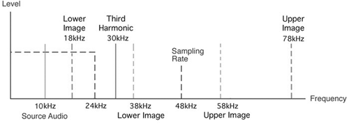
Of course, if the analog audio signal became clipped or distorted prior to the converter, then it would contain additional harmonics that could very well create audible aliasing. In Figure 2, a 10 kHz tone is distorted, creating a third harmonic at 30 kHz. When the harmonic modulates the 48 kHz sampling rate, it creates a lower sideband at 18 kHz, well within the audible range. This lower sideband may be too soft to hear, but at best it will add a harsh quality to the desired audio signal. This is just one of the reasons why it is so important to maintain adequate headroom when recording digital audio, and if it clips at the input then your best move is to simply do it over.
Removing these unwanted sidebands, including those just above the range of human hearing (like the 24.1 kHz sideband mentioned above), requires the use of another very steep low pass filter at the output of the digital to analog converter. A lowpass reconstruction filter at the output not only helps to smooth the reconstructed analog signal, but can also remove these sidebands. But like the anti-aliasing filter at the input, the reconstruction filter requires an extremely steep slope. Early versions of the reconstruction filter weren’t really up to the job of filtering outside bands at the low sample rates of the time. Not only did they often fail to remove the lower sidebands adequately, but they also affected the audio in a way that had unpleasantly audible side effects. Hence the complaint that early CDs sounded harsh and brittle.
The good news is that filtering technology has also advanced, and almost all modern digital audio equipment uses “Delta Sigma” converters. These converters operate internally at much higher sample rates than the rates at which the system itself is running. As a result, DSP designers have been able to build digital filters with extremely steep slopes that do not adversely affect the phase of the audio that passes through them.
Of course the move to record and edit at higher sample rates has had a similar effect on filter design. If you are recording at 88.2 kHz, or even higher, then the frequencies of the sidebands will be doubled, moving them yet further away from the audio, with the added bonus that the filters don’t have to work as hard.
Having said all that, it’s not clear that higher sample rates translate into noticeably higher quality sound (provided of course that the Nyquist theorem is not violated). Given that doubling the sample rate also doubles the file size on the hard disk (and quadrupling the sample rate obviously quadruples the file size), the jury is still out on whether audibly better quality justifies larger files. Most radio production people that I know are still working at 44.1 kHz.
DEEPER BITS
As I mentioned earlier, using a higher bit depth during the quantizing process generally results in greater dynamic range and a lower noise floor. But why? The answer lies in reducing quantization error.
Imagine building a birdhouse using a yardstick with only 12 tick marks on it. The yardstick would have a mark every 3 inches; so making a 2-inch or 4-inch measurement with this yardstick would be prone to error. Your birdhouse would be uninhabitable. The fact is that you need a yardstick whose tick marks are sufficient to measure the smallest increment you’ll use in building the birdhouse. The same is true in quantization.
The bit depth (also called “word length”) is the parameter that defines how many binary digits will be used to describe the instantaneous amplitude of a single sample. The more digits (or as we say, bits) that are available, the more accurate the amplitude measurement will be. Quantizing at a bit depth of eight bits gives only 256 different levels between softest and loudest. Quantizing at 16 bits gives a total of 65,536 discrete levels with which to measure instantaneous amplitude. At 24 bits, there are 16,777,216 levels available. So it would seem obvious that recording at 24 bits gives us more accuracy and a higher “resolution”. While that’s technically correct, it is somewhat misleading.
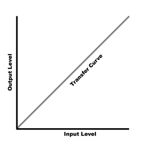
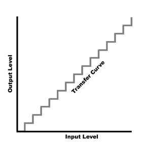
 In Figure 3 I’ve drawn a simple graph that shows the relationship between the input level and the output level in an analog system. At unity gain, the output level goes up in direct proportion to the input level, and the “transfer curve” is a straight line, or linear. Figure 4 shows the relationship between the input level and the output level in a quantized audio system. The transfer curve is stepped, because this quantizing system uses few bits. As the input level rises, nothing happens at the output level until the next bit is reached, when the output level suddenly jumps. As you might guess, the fewer the bits, the greater are the size of the steps.
The transfer curve is clearly non-linear, and what you would hear in the output would be distortion and buzz, particularly at low volume levels. This is quantization noise, and it’s important to note that it exists at some level no matter what the bit depth. Quantization error always creates a non-linear transfer curve, although the smaller the steps (and the higher the bit depth), the less quantization noise is generated. In fact, for every extra bit used in the quantization process, there will be 6 dB less quantization noise, and hence a 6 dB lower theoretical noise floor.
So how do we deal with quantization noise? The answer as you probably already know is dither. Dither helps to linearize the quantization process, by using noise to force the quantization process to jump between adjacent levels at random. The resulting transfer curve looks like a fuzzy straight line, and essentially gives us a linear system with some added noise.
 The good news is that we don’t need very much noise. The noise’s job is to randomize the turning on and turning off of the very last bit, so we only need one bit worth of noise. Of course one bit of noise in an eight-bit recording will be quite audible, while one bit of noise in a 16-bit recording will be down at approximately -96 dBFS. In a 24-bit recording the inherent noise of the analog electronics will be sufficient dither by itself.
Dither should always be used when converting 24-bit audio into 16-bit audio. Further, it should also be the very last action in the editing process. You don’t want to be editing dither or dithering a second time. The one notable exception to the “last action” rule is for fades. Several editors, including Pro Tools and Audition, have options that allow fades and cross fades to be dithered. In my opinion this is a good idea.
JITTER
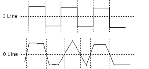
Lastly, let’s do a drive-by on the issue of jitter. Jitter is one of those topics that digital audio weenies love to discuss, and while it can be a serious problem, modern equipment designers and chip manufacturers have found effective ways of both preventing and dealing with it. In short, jitter is used to describe very short-term timing variations generated by a sample clock.

Figure 5 shows a very crude drawing of what can happen to a signal in a case of extreme jitter. If clock jitter is completely random then, while there will be some distortion, it too will be random, which makes it... noise. But clocking circuits today are so much better than in the past that this is just not a real-world problem. The one place where we still see jitter as an issue is with long cables. If you send a digital audio signal down a long cable, particularly if you use cheap wire or use audio RCA cables to move S/PDIF signals around, then you may hear aliasing or distortion in your digital audio, or perhaps random (and loud!) clicks and pops.
The solution in this instance is relatively simple: buy some proper cables, and when you connect multiple digital devices together, make the device with the AD and DA converters on it the master device. That way the one device that needs a clean clock most will have it, because it will be using its own internal clock.
WRAP
Given the fact that 24-bit digital audio gives the greatest dynamic range, has the lowest noise floor, and as a result gives you the greatest possible headroom, it’s no wonder that many of my friends in the business record and edit everything at 24 bits. Yes, there is a 50% larger file size penalty, but 50% isn’t much and hard drives are very, very cheap.
On the other hand, I have no reason so far to work in anything other than a 44.1 kHz sampling rate. That may change, but I now record and edit almost exclusively at 24 bit and 44.1 kHz, even for projects that will ultimately become CDs. There’s just no reason not to, and a very good reason to do it — headroom.
The lower noise floor of 24-bit audio also means you have more headroom. You can work at an average of -20 dBFS with 24-bit and get a quieter recording than you would at -8 dBFS using 16-bits. So add some bits, turn down the faders (turn up the amp!), and pick up a bigger hard drive. You’ll be glad you did.
♦

