by Steve Cunningham
This month we’re going to tackle a number of terms that you have likely encountered on a plug-in, a piece of signal processing hardware, or a workstation. Many of us learn what these things do (or don’t do) via a trial and error process, or maybe we read about them in the manual (yeah, right!). But although you may know what the effect is, you may not know how or why it works the way it does.
Hopefully this piece will fill in some gaps for you.
LOOK-AHEAD COMPRESSOR
Here’s a function you’ll encounter primarily in software compressor plug-ins, because it’s a pain to do in hardware. In short, a look-ahead compressor actually begins compressing before the transient signal hits the amplifier in the compressor. No, the compressor is not psychic... but there is a bit of a trick involved.
As you know, a compressor’s job is to decrease the total dynamic range of audio by turning the loud parts down. This allows us to then turn up the entire compressed audio track, giving us a more present, in-your-face sound.
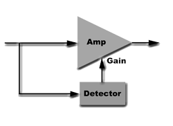
 The compressor does this job by splitting the input signal into two paths (see figure 1). One goes to the input of an amplifier, while the other goes to a detector that measures the level of the incoming signal. For the solder jockies amongst you, there are several ways to measure incoming signal level, from diode networks to light/phototransistor pairs. In any event, the output of the detector is a voltage that is applied to the gain control of the amplifier.
When a loud transient hits the detector, it turns the amplifier down.
Now this is all well and good, but it should be evident that the onset of the transient will probably be sent through the amplifier at the normal gain, since it takes some amount of time for the detector to detect, and for the detector’s output to turn down the amplifier.
We’re talking about perhaps the first several milliseconds, but it will get through.
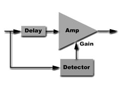
 In the analog days, engineers dealt with this problem by inserting a delay in front of the amplifier, but after the split point of the incoming audio (see figure 2). This allowed the detector to begin turning down the amplifier slightly before the onset of the transient hit the amplifier, making sure that the entire transient was caught and reduced in volume. This delayed the audio track coming out of the amplifier relative to anything else playing, of course. The only way to fix that problem was to delay everything else by the same amount. The whole business worked, but it was a bit messy.
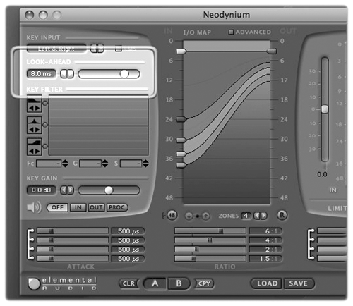
Today’s digital compressors often feature a look-ahead function, usually adjustable up to 10 milliseconds or so (see figure 3). If you engage the look-ahead function, be aware that the output of the compressor is delayed by the amount of the look-ahead.
It does ensure that the onsets are all caught, at the expense of the output delay. Look-ahead is applied by mastering engineers to get the smoothest possible compression through the mastering process, where the output delay is inconsequential. For general production use I find little use in look-ahead except with extremely dynamic music and sound effects, but now you know what it is and does.

LINEAR PHASE EQ
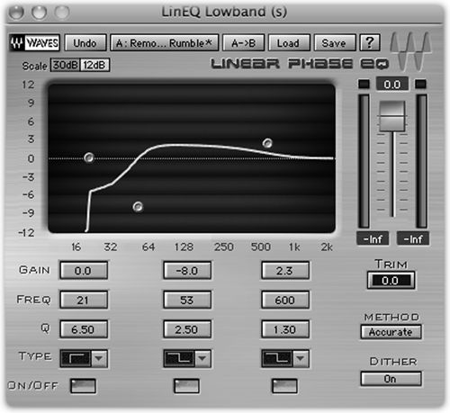
A linear phase equalizer is a specialized digital filter which does not impart any phase shift to the total signal (see figure 4). You may now be thinking “Thanks, Captain Obvious. But I still don’t get it.” The fact is that all equalizers mess with the phase of your audio to some extent, and here’s why. Old-school equalizers consisted of capacitors and inductors, which shift the phase of any AC signal that passes through them, including audio. So, sending some signal through these components and then combining it with the original signal results in audio whose frequency response is altered by the reinforcement and cancellation that occurs at specific frequencies. The fact is that without phase shift, analog equalizers would not work at all.

Digital equalizers mimic the behavior of analog equalizers using a completely different methodology. Instead of using capacitors and inductors to shift phase, they use taps on a digital delay line. Think tape delay using a tape recorder with one record head and multiple play heads on it. Each sound recorded on tape is available for playback at each of the subsequent play heads in turn as the sound on tape passes them. The taps on a digital delay are like the play heads, except that they are actually memory locations that store digital audio words, and are passed down the line from location to location.
These transfers occur on each clock cycle which is normally the sample rate, so there would be 44,100 clock cycles per second.
This is the basis for a digital delay, and you can alter the delay time by changing the total number of locations each number passes through, or by changing the sample rate, or both. A series of memory locations used for this purpose is sometimes called a shift register because of the way the numbers are shifted through them.
To create an equalizer from a digital delay line you tap into one of the intermediary memory locations and feed a varying amount of that digital signal back to the input. This is the equivalent of feedback or regeneration on an echo device. The tapped digital signal combines with the input to create a boost. You can also reverse the polarity of the tapped signal before sending it back to the input to get a cut. So the delayed sound combines with the dry sound to create peaks and dips in the frequency response. By controlling which memory locations along the delay route you tap into, how much of the tapped signal is fed back into the input, and whether or not the polarity is reversed, you create an equalizer.
Wonderful. But the digital process has changed the phase of the original signal in much the same way as does an analog equalizer. Some degree of phase shift occurs as the signal goes through the digital equalizer.
Linear phase equalizers eliminate this phase shift with some serious algorithms, along with some delay applied to the input signal before it’s combined with the signal from the taps. Like the look-ahead function on a compressor, linear phase equalizers are favored by mastering engineers who want to be able to make frequency adjustments with as little impact on the stereo imaging as possible.
Having said all that, the phase shift that occurs in regular digital (and analog!) equalizers is overhyped by some. Some people confuse the sound of phasers and flanger effects with the phase shift in equalizers. But those effects use phase shift to create comb filtering, which in turn really does alter the frequency response.
Comb filtering is what you hear when you run a track through a Flanger. It’s the series of peaks and dips in the frequency response that drastically changes the sound. Phase shift in equalizers is blamed for a host of other problems and phenomena.
Some people claim they can hear phase shift in equalizers, because when they boost the treble they hear a “swooshy” sound. But what they are hearing is comb filtering that was already present at a very low level. For example, when a microphone is near a room boundary like a wall or ceiling, the delay between the direct and reflected sound creates a comb filter acoustically in the air. When the treble is boosted by EQ, the comb filtering becomes more apparent. The EQ did not add the “swoosh”, it merely brought it out.
The same thing can happen when mixing tracks recorded with multiple microphones in a room and one actor’s VO bleeds into the other’s mic.
When the VO tracks are played together it’s possible for the low end to be boosted or reduced by the acoustic interference caused by the arrival time difference between mikes. So while phase shift is indeed the cause of the response change, it’s the response change that you hear, not the phase shift itself.
But again, for normal production use there’s no real reason to spend the extra money for a linear phase equalizer. On the contrary, companies like SSL not only admit that their equalizers create phase shift, but declare that the result is musically pleasant and help create the signature “SSL sound”. Or so they say.
DITHER SHAPING
Also referred to as “noise shaping” or “noise-shaped dither”, this parameter describes the type of dither that will be added to the audio signal. It turns out that some kinds of noise are better than others.
As you’ll recall from last month, dither is literally noise that is added to digital audio to hide quantization error. It’s most commonly used when converting 24-bit audio to 16-bits so it can be used on a CD. It not only reduces the audible “buzz” of quantization error that appears in very soft sounds, but it lets us better hear digital audio that is very soft. This occurs because we can often hear the desired audio under the dither noise, whereas the “buzz” of quantization noise will either bury the desired sound or cause the converters to mute altogether.
Regular dither consists of random values -- which of course is noise in both the analog and digital domains -- that together sound like white noise to our ears. Recognizing that our ears are more sensitive to midrange frequencies than to either low or high frequencies, we can add dither that contains less midrange frequencies and more low and high frequencies. The result as regards quantization error is the same... it is reduced, and we hear more of the desired audio, while the lack of midrange in the dither means we don’t hear as much hiss as we might with dither that is not noise-shaped.
Changing the frequency content of the dither to make it less audible is exactly how Apogee’s UV-22 and UV-22HR dither work. Both consist of filtered noise that is less objectionable to our ears than is regular dither. The POW-R dither algorithms take the process one step further, in that the software actually analyzes the quantization error and adjusts the dither to maximize its ability to actually cancel out the audible quantization error. The POW-R Consortium claims this actually reduces quantization error by about 6dB.
For normal production work, the choice between regular and noise-shaped dither is up to you and to your ears. I tend to use noise-shaped dither, but only because I have used it in the past with good results. The more important issue here is that you use dither whenever you convert the bit rate from 24-bits down to 16-bits. While you probably will not notice a difference based on which flavor you use, you will definitely notice a difference if you don’t use it at all. It won’t be a pretty difference, either.
RT60
This is an oldie but a goodie... you’ll see this parameter on some reverb plug-ins, and it defines the length of the reverb tail in terms of level. In actuality it is a measure of how long it takes for an acoustic sound to decay in a room.
The RT part stands for Reverb Time, and the 60 portion of it refers a -60 dB decrease in level. For all intents and purposes -60 dB is close to silence, so it’s a more accurate measurement of the reverb response and tail length than the simpler but more common Decay parameter, in that it takes into account both the virtual size of the room, but also the surface absorption of the room and the materials within it.
♦

